
TM 1-2840-252-23-3
G-26
FAULT CODE Al, Q SENSOR EXPANDED INSTRUCTIONS
Refer to numbered steps in figure 112.
Step 3.
Check harness connector PL1 (figure 201) at DECU, and P2 at signal conditioner for tight
connections.
Step 4.
Disconnect connectors PL1 and P2 to check pins and sockets.
Step 6.
With PL1 and P2 disconnected, short P2 connector sockets D and K together. Check resistance at harness
PL1 connector sockets H and J (figure 202). Limit is < 1Q.
Step 7.
Refer to manufacturer's procedure for checking operation of engine torquemeter components.
Step 8.
Before tightening harness connectors PL1 and P2, be sure that keyways in harness connectors are aligned
with keyways in component connectors.
Step 14.
Refer t- manufacturer's procedure for diagnosing and replacing harness or signal conditioner.
Step 16.
Refer to manufacturer's procedure for diagnosing and replacing harness.
Step 18
Refer to manufacturer's procedure for diagnosing and replacing engine torquemeter components.
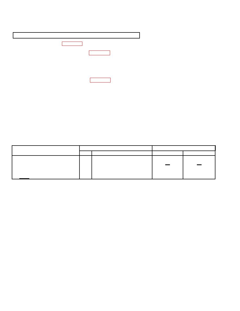
RESISTANCE-CHECK SUMMARY
Resistance (Ω)
Connector
Component
No.
Contacts
Limits
Nominal*
<1
<1
Q Sensor Harness
PL1
H&J
(with P2 D & K shorted)
*At 25
C
G-49
