
TM 1-2840-252-23-3
G-19 FAULT CODE F5 Wf/STEPCOUNT DIFFERENCE EXPANDED INSTRUCTIONS
Refer to numbered steps in figure 105.
Step 2.
Check harness connector PL1 (figure 201) at DECU, and P4 at HMA for tight connections.
Step 3.
Disconnect connectors PL1 and P4 to check pins and sockets.
Step 5.
With PL1 disconnected, check resistance of HMA (primary stepper motor) at harness PL1
connector sockets T and X (figure 202), U and X, V and X, and W and X. In each case limit is
45-111Q.
Step 6.
With P4 disconnected, check resistance of (primary stepper motor) at HMA J4 connector.
pins D and T, C and T, B and T, and A and T. In each case,.limit is45-111Q.
Step 7.
Before tightening harness connectors PL1 and P4, be sure that keyways in harness connectors
are aligned with keyways in component connectors.
Step 12. Refer to manufacturer's procedure for diagnosing and replacing harness.
Step 17. Refer to manufacturer's procedure for diagnosing and replacing harness.
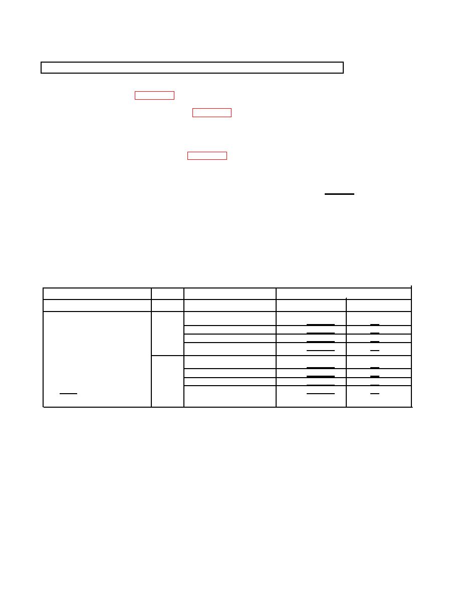
RESISTANCE-CHECK SUMMARY
Resistance (Ω)
Connector
Component
No.
Contacts
Limits
Nominal*
HMA - Primary Stepper Motor
PL1
T&X
45 - 111
73
U&X
45 - 111
73
V&X
45 - 111
73
W&X
45 - 111
73
J4
D&T
45 - 111
73
C&T
45 - 111
73
B&T
45 - 111
73
* At 25
C
A&T
45 - 111
73
G-27
