
TM 1-2840-252-23-3
G-17 FAULT CODE F3, NIA/NIB DIFFERENCE EXPANDED INSTRUCTIONS
Refer to numbered steps in figure 103.
Step 4.
Check harness connectors PL1 and PL3 (figure 201) at DECU, and P4 and P6 at HMA for tight
connections.
Step 5.
Disconnect connectors PL1, PL3, P4 and P6 to check pins and sockets.
Step 7.
With PL1 disconnected, check resistance of HMA (N1A sensor) at harness PL1 connector
sockets MM and FF (figure 202). Limit is 200-550Q. With PL3 disconnected, check resistance
of HMA ( N1 B sensor) at harness PL3 connector sockets A and c. Limit is 0.3-3.5o2.
Step 8.
With P4 disconnected, check resistance of HMA (N1A sensor) at HMA J4 connector pins R and
S. Limit is 200-550Q. With P6 disconnected, check resistance of HMA (N1 B sensor) at HMA
T. J6 connector pins E and F. Limit is 0.3-3.3Q.
Step 9.
Before tightening harness connectors PL1, PL3, P4 and P6, be sure that keyways in harness
connectors are aligned with keyways in component connectors.
Step 13. Refer to manufacturer's procedure for checking drive pad and spline.
Step 18. Refer to manufacturer's procedure for diagnosis and replacing harness.
Step 21. Refer to manufacturer's procedure for replacing drive pad or spline.
Step 23. Refer to manufacturer' procedure for diagnosing and replacing harness.
s
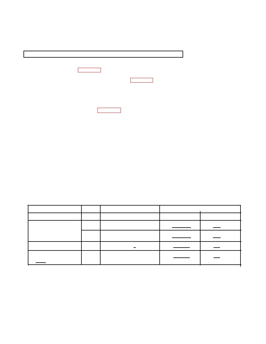
RESISTANCE-CHECK SUMMARY
Resistance (Ω)
Connector
Component
No.
Contacts
Limits
Nominal *
HMA - N1A Sensor
PL1
MM &FF
200 - 550
390
J4
R&S
200 - 550
390
HMA - N1A Sensor
J4
A-c
0.3 - 3.5
0.7
J6
E&F
0.3 - 3.0
0.7
*At 25
C
G-20
