
TM 1-2840-252-23-2
4-57
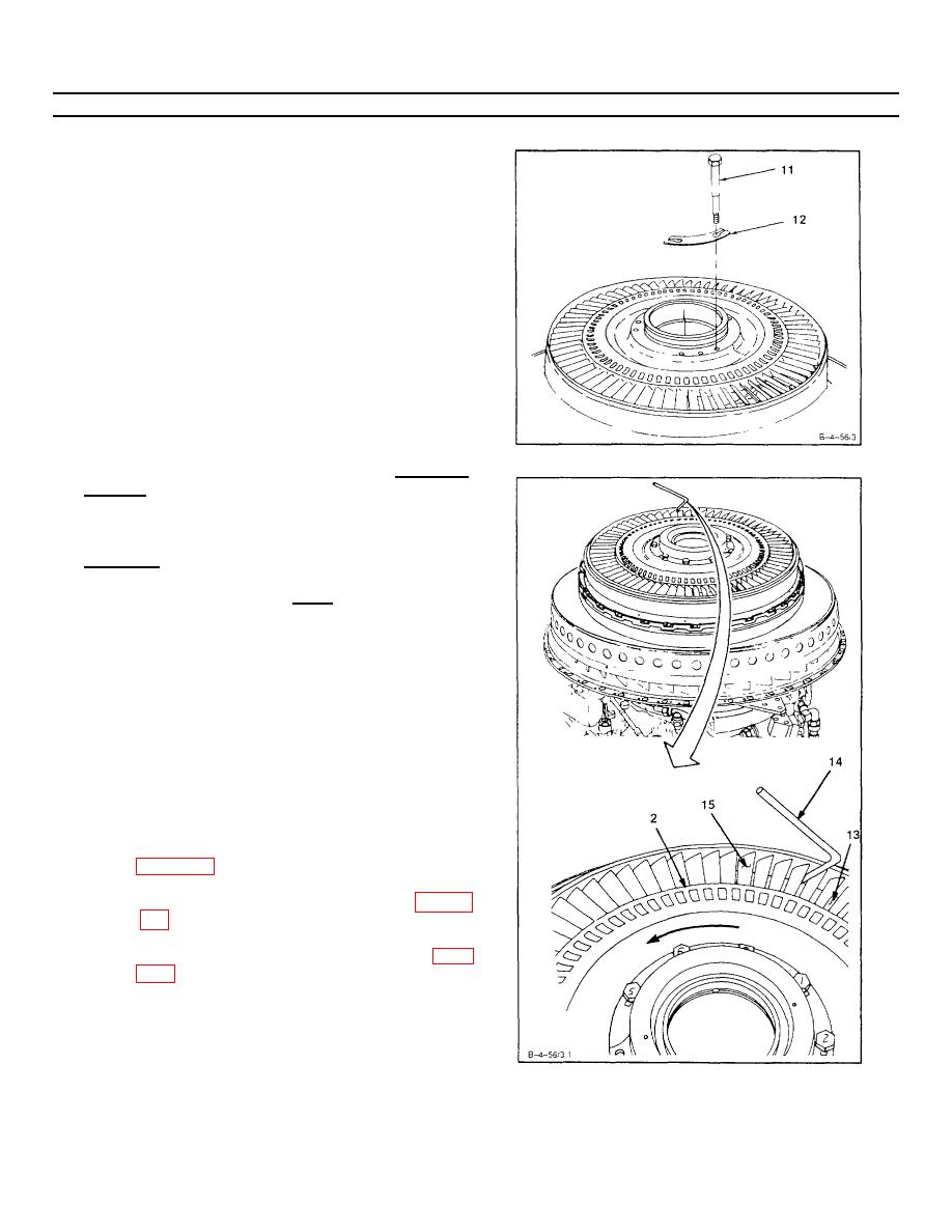
INSTALL SECOND TURBINE DISC ASSEMBLY (AVIM) (Continued)
4-57
9. Coat threads of six bolts (11) with anti-seize compound
(E6)
NOTE
Do not bend up tabs of locking plates.
NOTE
Bolts must be installed in accordance with index
numbers marked on bolt heads and second turbine
disc assembly. If any of the six bolts are lost, all
six bolts must be replaced and a vibration test
performed (Ref. TM 1-1520-252-23).
10. Install new locking plates (12) and bolts (11) on
second turbine disc assembly.
11. Stagger tighten bolts (11).
Torque to 155 inch-
pounds.
12. Check axial clearance between second turbine disc
assembly (2) and second turbine nozzle (13). Use
0.225 inch bent wire gage (Appendix E) (14) inserted
between blades (15) of second turbine disc assembly
(2). Axial clearance shall be0.225 inch minimum.
INSPECT
NOTE
If axial clearance is not within limits, do all steps.
If axial clearance is acceptable, omit steps a. thru
c..
a. Recheck first turbine disc assembly installation
procedure as follows:
(1) Remove second turbine disc assembly (Ref
(2) Remove second turbine nozzle (Ref Task 4-
(3) Remove first turbine disc assembly (Ref Task
GO TO NEXT PAGE
4-304
