
TM 1-2840-252-23-2
4-36
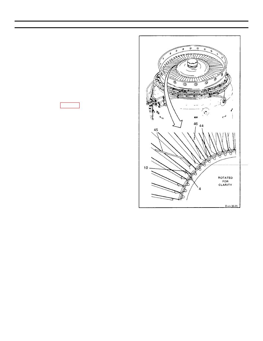
INSTALL FOURTH STAGE POWER TURBINE ROTOR (AVIM) (Continued)
4-36
25. Check axial clearance between fourth stage power
turbine rotor (4) and fourth stage power turbine nozzle
(10) at blade roots (44). Use 0.104 inch and 0.228 inch
bent wire gage (Appendix E) (44) inserted between
fourth stage power turbine rotor blades (46). Axial
clearance shall not be less than 0.104 inch or more
than 0.228 inch.
NOTE
If axial clearance is not within limits, do
steps 14 thru 25. Ring spacer may be
installed or removed as necessary.
Recheck clearance. If clearance still is
not within limits, replace power turbine
assembly (Ref Tasks 3-6 and 3-7).
GO TO NEXT PAGE
4-161
