
TM 1-2840-252-23-2
4-36 INSPECT FOURTH STAGE POWER TURBINE ROTOR (AVIM) (Continued)
4-36
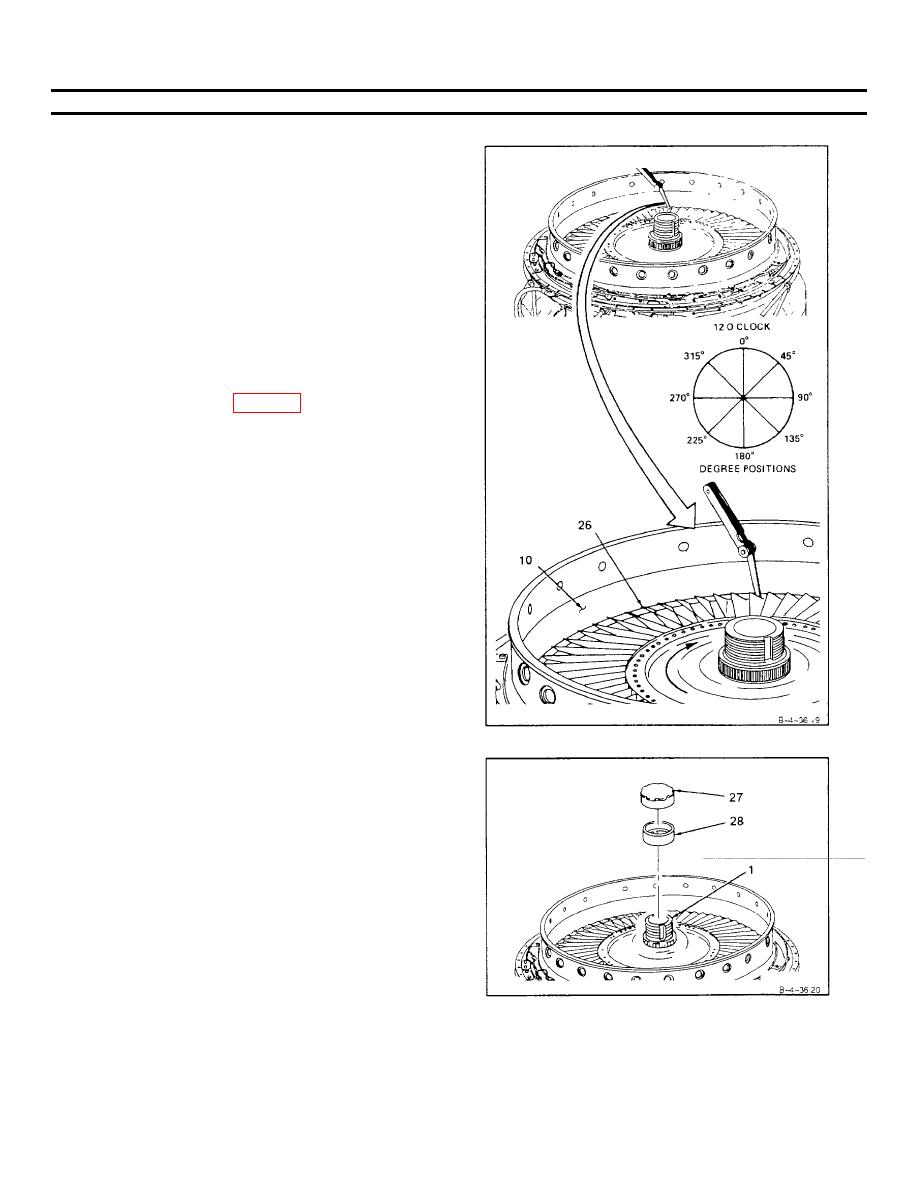
18. Measure clearance between blade tips (26) and fourth
stage power turbine nozzle (10) (tip clearance)at 0,
45, 90,135, 180, 225, 270, and 315 degree positions as
follows.
a. Insert thickness gage between fourth stage power
turbine nozzle (10) and blade (26) tip Rotate fourth
stage turbine rotor (4) clockwise one revolution for
each check
b. Tip clearance shall be 0 020 inch minimum.
NOTE
If tip clearance is not within limits, replace power
turbine assembly (Ref Tasks 3-6 and 3-7)
19. Coat threads of nut (27) with anti-seize compound (E6)
Install serviceable locking cup (28) and nut (27) on
shaft (1).
GO TO NEXT PAGE
4-155
