
TM 1-2840-252-23-2
3-8
INSTALL COMBUSTION SECTION AND POWER TURBINE (AVIM) (Continued)
3-8
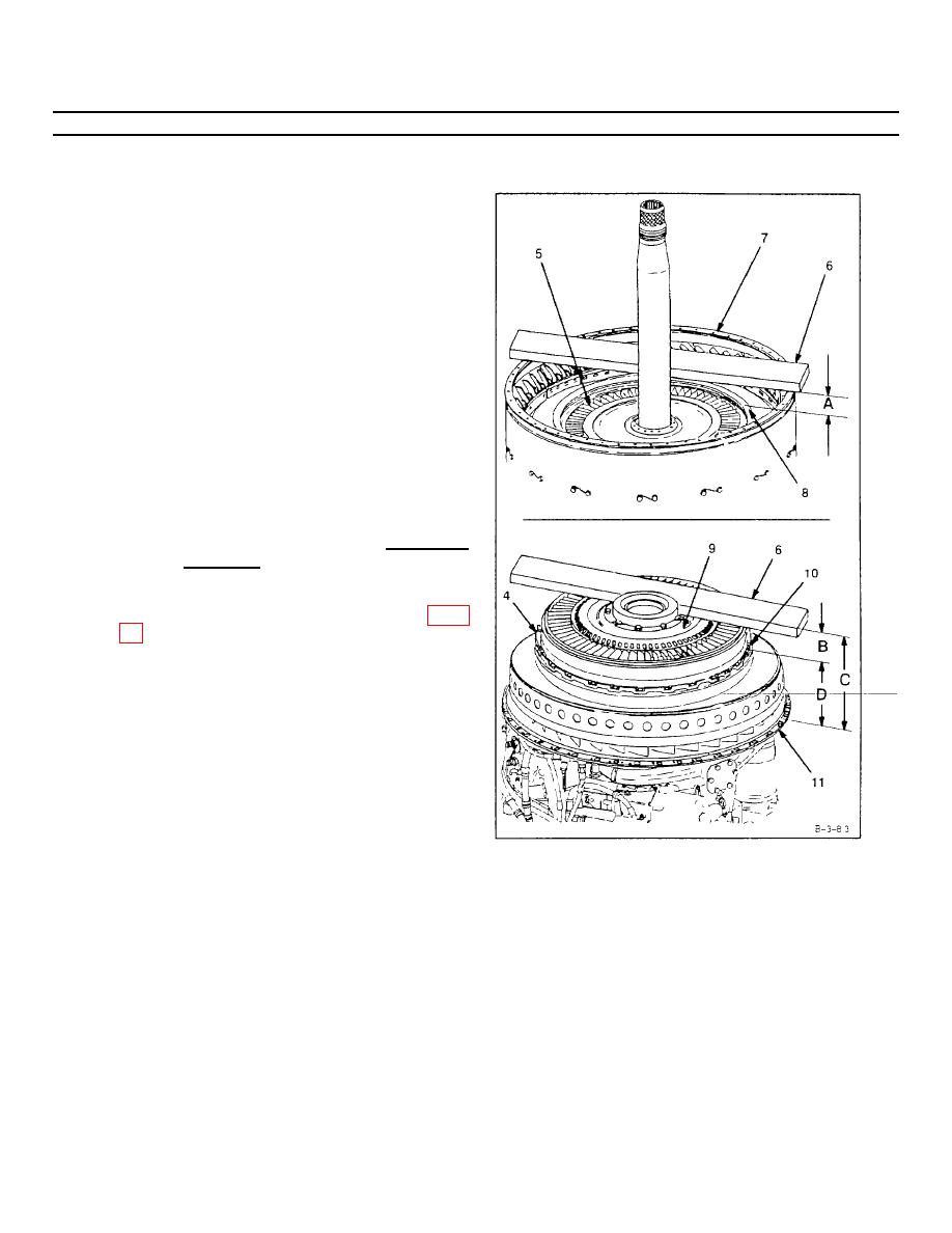
2.
Calculate bumper fit between second turbine
nozzle bumper (4) and third turbine nozzle (5) as
follows:
a.
Place locating bar (T33) (6) on combustion
chamber mounting flange (7). Measure from top
of locating bar (T33) (6) to third turbine nozzle
outer support (8) Subtract thickness of locating
bar (T33) (6). Record as dimension A.
b.
Place locating bar (T33) (6) on second turbine
disc assembly aft face (9). Measure from top of
locating bar (T33) (6) to top of bumper (10).
Record as dimension B. Measure from top of
locating bar (T33) (6) to air diffuser outerflange
(11) Record as dimension C. Subtract dimension
B from dimension C. Record result as dimension
D.
c.
Subtract dimension D from dimension A Result is
bumper fit. Bumper fit shall be 0.040 inch
loose to 0.040 inch tight.
If bumper fit cannot be met, replace power
d.
INSPECT
GO TO NEXT PAGE
3-97
