3.
4.
5.
6.
7.
8.
9.
100
11.
TM 55-2835-208-23
2-101 REMOVE DRIVE SYSTEM (Continued)
2-101
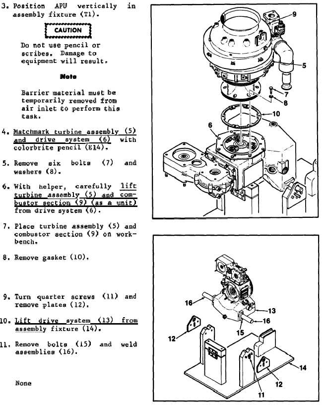
Position
APU
vertically
in
assembly fixture (Tl).
Do not use pencil or
scribes.
Damage to
equipment will result.
Note
Barrier material must be
temporarily removed from
air inlet to perform this
task.
Matchmark turbine assembly
(5)
and
drive
system
(6)
with
colorbrite pencil (E14).
Remove
six
bolts
(7)
and
washers (8).
With
helper,
carefully
lift
turbine assembly (5) and =
bustor section (9) (as a unit)
from drive system (6).
Place turbine assembly (5) and
combustor section (9) on work-
bench.
Remove gasket (10).
Turn quarter screws
remove plates (12).
(11) and
Lift
drive
system
(13)
from
assembly fixture (14).
Remove
bolts
(15)
and
weld
assemblies (16).
FOLLOW-ON MAINTENANCE:
None
END OF TASK
2-184